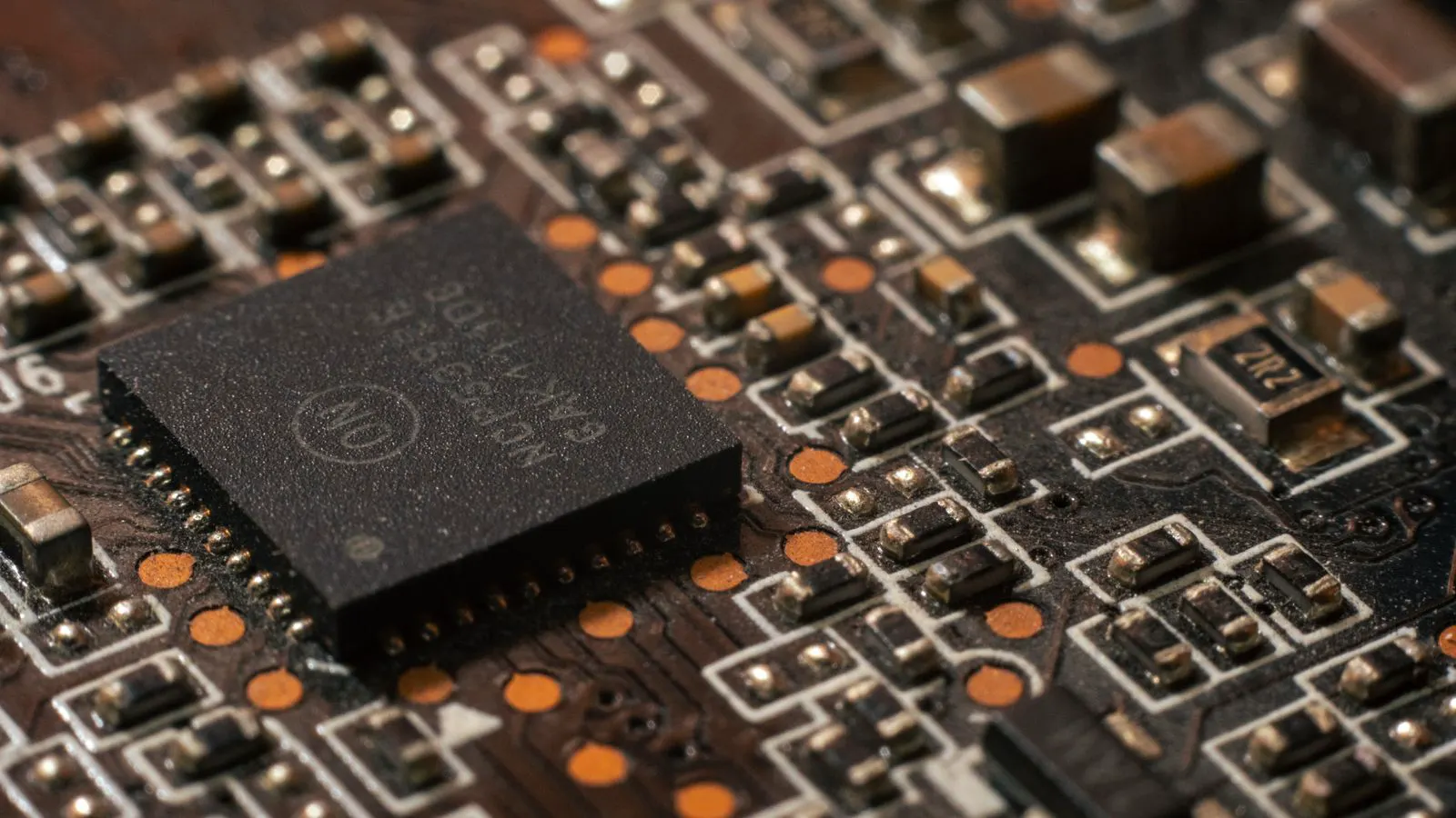
Spotting fake SMD resistors requires a systematic approach. Inspect the die, coating, and packaging for visual defects. Verify weight and markings against datasheets. These physical checks reveal inconsistencies that automated scanners might miss before parts reach the reflow oven.
- Check the die material and coating color for inconsistencies with supplier samples.
- Weigh parts in small batches to identify density variations common in counterfeit materials.
- Examine packaging for date codes, batch numbers, and seal integrity.
- Compare physical dimensions to datasheet specifications using a microscope or caliper.
- Maintain a baseline of known good samples for quick visual comparison during incoming inspection.
Why Physical Inspection Still Matters
Automated testing catches many electrical faults, but it often misses the subtle physical changes that signal a counterfeit part. A fake resistor may pass a basic continuity check while still failing during reflow. The metal body, die coating, or termination finish might differ from the original design. These variations cause solder joint issues, thermal stress, or long-term reliability failures.
Buyers and engineers need a repeatable method to spot these problems before assembly. This guide covers the practical steps you can take in a receiving dock or inspection bench. It focuses on what you can see and feel without specialized lab equipment.
Automated optical inspection systems on production lines are excellent at detecting missing parts, bridging, or misalignment. They are not always tuned to detect material substitution. A counterfeit chip may have the exact same footprint and pin count. It may even pass a basic ohmic check. The difference lies in the materials used to build the component. A cheaper ceramic substrate, a thinner die layer, or a non-conformant solder mask can change the thermal expansion coefficient. When the board goes through a high-temperature reflow cycle, these parts can crack, delaminate, or suffer from intermetallic compound formation issues.
Physical inspection is the first line of defense. It is low cost, fast, and requires only basic tools. It acts as a gatekeeper. If a part fails the physical checks, it does not reach the soldering station. This prevents expensive rework and protects the integrity of the final product. You do not need a laboratory to perform these checks. A well-lit bench, a good magnifier, and a digital scale are sufficient to catch the most common forms of substitution.
Visual Inspection of the Die and Coating
The die is the core of the resistor. It sits under the plastic coating and determines the electrical behavior. Look at the color of the die under a magnifier. Authentic parts usually have a consistent, opaque finish. Counterfeits often show a lighter, grayish, or uneven coating. You might see visible particles, bubbles, or a shiny sheen that does not match your approved sample.
Check the ends of the die. The metal termination areas should be clean and uniform. If the coating looks like it was applied in a second pass, or if there is a visible boundary between the die and the body, suspect the part. Some fakes use a different adhesive or coating material that cures differently. This can make the part look brittle or discolored.
Compare the color bands. While the band colors indicate values, the print quality matters. Authentic printing is sharp and aligned. Counterfeit bands may be blurry, misaligned, or use a different ink that fades under UV light. If you have a reference sample, place the new part next to it. The difference is often obvious when you compare the two side by side.
For through-hole resistors, the body is often ceramic or a polymer composite. The finish should be matte and consistent. Counterfeit parts may have a glossy finish that suggests a cheap plastic body. This material has a higher coefficient of thermal expansion. It will not handle the thermal cycling of a power application as well as the original ceramic.
For surface-mount devices, the die is often covered by a thin layer of epoxy or a plastic overmold. Look for the “die line”. This is the visible boundary where the active material meets the overmold. In a genuine part, this line is sharp and clean. In a counterfeit, the die may appear to have been pressed into a pre-formed shell. You might see gaps or voids at the interface. These voids trap moisture. Over time, the moisture migrates into the die, causing a change in resistance value or complete failure.
Also check for stress marks. If a part has been handled roughly or stored improperly, the coating may show hairline cracks. These cracks are not always visible to the naked eye. Under a 10x loupe, they appear as dark lines running across the body. While a single crack may not be a deal-breaker, multiple cracks suggest poor handling or a brittle material that does not withstand thermal stress.
Checking Weight and Density
Weight is a simple but effective check. SMD resistors are small, but a scale can detect density changes. Counterfeit parts often use cheaper die materials or less dense coatings. This changes the mass. Set a tolerance range based on your known good samples. If a batch weighs significantly more or less than expected, hold it for further review.
Do not rely on a single part. Weigh five to ten parts from different locations in the package. Take the average. This smooths out individual manufacturing variations. If the average falls outside your established range, the material is likely different. This method is especially useful for high-volume parts where subtle changes are hard to see with the eye.
You can also check the body dimensions. Use a digital caliper or a microscope. Measure the length, width, and height. Counterfeits often have slightly different body sizes to make the part fit a different die or coating process. Even a fraction of a millimeter difference can affect placement accuracy in automated assembly.
Consider the mass-to-volume ratio. If you know the nominal mass of a genuine part, you can calculate the expected density. A significant deviation in mass for the same volume indicates a change in material composition. For example, a ceramic die is denser than a plastic die. If a part is lighter than expected, the manufacturer may have substituted the ceramic body with a polymer composite. This substitution saves cost but compromises reliability.
Use a high-precision scale. For SMD resistors, a scale that measures in milligrams is required. The difference between a genuine part and a counterfeit can be as small as one or two milligrams. Record the weight of each sample. If the weight drifts over time, it may indicate a change in the manufacturing process. This is a strong signal to contact the supplier and request a process audit.
Packaging and Marking Review
The package tells a story about the supply chain. Look at the tape reel or tray. Check the date codes and batch numbers. These should be consistent across the package. If the dates vary widely, or if the batch number is missing, be suspicious.
Inspect the seal. Authentic packages often have a tamper-evident seal or a specific adhesive tape. If the tape is loose, the label is peeling, or the packaging looks resealed, the contents may have been opened. Check the label quality. Authentic labels have crisp text and correct part numbers. Counterfeit labels may have typos, blurry printing, or incorrect formatting.
Verify the documentation. Match the packing slip, certificate of conformance, and datasheet against the physical part. The part number on the label must match the markings on the resistor. If there is a discrepancy, stop. Do not assume it is a printer error. Confirm with the supplier before proceeding.
Look for the “dot” or “cross” marks on the tape. These are used by automated feeders to identify the start and end of the tape loop. If the tape is re-rolled by an unauthorized party, the dots may be misaligned or missing. This indicates that the tape was cut and re-spliced. The parts inside may have been mixed with other batches or even with counterfeit units.
Check the humidity indicator card. If the package has been opened, the card will show a change in color. This indicates exposure to moisture. Moisture exposure can cause corrosion of the terminations or a change in the die properties. Even if the card looks normal, the packaging may have been resealed. Look for wrinkles in the tape or a lack of tension on the seal.
Tactile and Handling Checks
Pick up the part. Feel the body. Authentic SMD resistors have a smooth, uniform surface. Counterfeits may feel rough, uneven, or brittle. The coating should not chip or flake under light pressure. If the part feels hollow or light, the internal die may be different.
Check the terminations. The metal pads should be flat and consistent. If they are curled, uneven, or have a different color, the plating process may be different. This affects soldering performance. You might notice that the part does not sit flat on the PCB. This causes solder bridging or poor joint formation.
Listen to the sound. Place a few parts on a hard surface and tap them gently. Authentic parts have a solid, dense sound. Counterfeits may sound hollow or produce a different tone. This is a subtle check, but it can help identify material changes.
Handle parts with care. Use tweezers or a pick-and-place tool. Do not touch the terminations with your fingers. Skin oils and salts can contaminate the pads. This makes soldering difficult and can cause cold joints. If you are doing manual inspection, use clean gloves. This preserves the cleanliness of the parts for the next step.
Check the flexibility of the body. Gently bend the body of a through-hole resistor. It should have a slight give. If it snaps or feels brittle, the material is likely not the intended ceramic composite. Brittle bodies are more prone to cracking during assembly. This is a common failure mode in low-quality substitutes.
Common Symptoms and Likely Causes
| Symptom | Likely cause | What to do |
|---|---|---|
| Die coating looks gray or uneven | Different die material or coating process | Hold for supplier confirmation and compare with known good samples. |
| Part weight is outside tolerance | Density change in body or die material | Weigh a larger sample and check batch documentation. |
| Band printing is blurry or misaligned | Different printing process or lower quality materials | Inspect under magnification and check for ink consistency. |
| Packaging seal is loose or missing | Potential tampering or re-packaging | Verify batch numbers and date codes against supplier records. |
| Body dimensions differ from datasheet | Different die size or coating thickness | Measure with a caliper and compare to approved sample. |
| Terminations are uneven or discolored | Different plating process or material | Check solderability and review supplier process documentation. |
Prevention Tips for Incoming Inspection
- Maintain a library of known good samples. Keep sealed packages from approved suppliers in a secure area. Use these for side-by-side comparison during every incoming inspection.
- Establish a weight baseline. Weigh a sample from each new batch. Record the average and tolerance. If the weight shifts, investigate before assembly.
- Use a magnifier or microscope. A 5x or 10x loupe is enough to see die coating issues and band alignment. Train your team on what to look for.
- Check the entire package. Do not just inspect the part. Review the tape, tray, labels, and documentation. Inconsistencies in packaging often point to counterfeit parts.
- Keep a record of inspections. Log the part number, batch, date, and inspection results. This helps you spot trends and hold problematic batches.
- Communicate with suppliers. If you find a discrepancy, contact the supplier immediately. Provide photos and measurements. Ask for a corrective action plan.
When to Escalate
If you find multiple red flags, do not assume it is a one-off issue. Counterfeit parts often come in batches. If one part fails, test the entire batch. If the batch fails, stop using it. Contact the supplier and request a return or replacement.
If the supplier cannot provide documentation or confirm the part origin, escalate the issue. Consider sourcing from a different distributor. Do not risk your assembly line with parts of unknown origin. The cost of a few minutes of inspection is far lower than the cost of a field failure or a production stop.
Escalation is not just about the current batch. It is about the supply chain integrity. If a supplier cannot provide traceability, they are not a reliable partner. You need a supplier who can tell you where the part was made, who made it, and what materials were used. If they cannot answer these questions, the risk is too high.
Document the escalation. Write a formal email to the supplier. Include photos of the defects, the batch numbers, and the date of receipt. Request a formal response. If the supplier does not respond or provides a vague answer, terminate the relationship. Find a new source. The transition may take time, but it is safer than continuing to use suspect parts.
Final Thoughts
Spotting fake SMD resistors is about attention to detail. You do not need expensive equipment. A magnifier, a scale, and a reference sample are enough to catch most issues. Focus on the die, the coating, the weight, and the packaging. These physical checks reveal inconsistencies that automated scanners might miss. By building a routine of physical inspection, you protect your assembly and your reputation.
This routine is not a one-time task. It is a continuous process. As new suppliers come online, you need to update your reference samples. As new counterfeit techniques emerge, you need to update your inspection criteria. Stay informed. Attend industry meetings. Talk to other engineers. Share your findings. The more you know, the better you can protect your supply chain.
Frequently asked questions
Can I detect counterfeit SMD resistors with just the naked eye?
Some signs are visible without tools, such as band alignment or packaging issues. However, a magnifier or microscope is recommended to see die coating variations and subtle material changes.
What is the best way to verify the part number on a resistor?
Compare the markings on the part to the datasheet and packaging labels. Check the font, color, and alignment. If there is a discrepancy, hold the part for further review.
How often should I weigh a batch of SMD resistors?
Weigh a sample from each new batch. If the part is high-value or from a new supplier, weigh every batch. This helps you catch material changes early.
Can counterfeit parts pass an electrical test?
Yes. Many fakes pass basic continuity or resistance checks. Physical inspection is needed to catch material and structural differences that may not show up in electrical testing.
What should I do if I find a suspected counterfeit part?
Hold the part and the batch. Do not use it. Contact the supplier with photos and measurements. Request a certificate of conformance and a corrective action plan.